MedICal ultrasound systems are among the more sophisticated signal processing machines in widespread use today. Though analogous to radar or sonar, they operate at RF speeds that are orders of magnitude slower than radar and faster than sonar. Since the development of early cart-based ultrasound systems, the medical industry has used this real-time technology for both early detection of health problems and general diagnostic procedures. Over time, ultrasound systems have become increasingly portable, with some even evolving into ultracompact palm-sized devices. In the not-so-distant future, an ultrasound system could become a specialized personal digital assistant (PDA)—though not quite as common as the doctor’s stethoscope. We will discuss here some of the necessary ingredients of compactness.
Ultrasound System Architectures
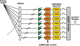
A commonly used approach to image acquisition in ultrasound systems is digital beamforming (DBF). Beamforming, as applied to medical ultrasound, is defined as the phase alignment and summation of signals that are generated from a common source, but received at different times by a multi-element ultrasound transducer. With arrays of 16 to 32 (or more) receiver channels phase-shifted and summed together to extract coherent information, beamforming has two functions: it imparts directivity to the transducer—enhancing its gain—and defines a focal point within the body, from which the location of the returning echo is derived. In its simplest state, a DBF system block diagram can look something like Figure 1. The output of each sensor element is amplified, converted to digital, and arranged in sequence. Multiple channels are spatially summed to develop an image.

DBF architectures are preferred over earlier analog beamforming systems (ABF)—which use variable delay lines and analog summation before conversion—because they tend to have better channel-to-channel matching characteristics and are more flexible. once the signal is acquired, its quality can be enhanced by performing digital operations such as beam steering and coherent signal summation. Bringing the digital engine closer to the ultrasonic sensors enables significantly finer adjustments to be made than could be achieved in the analog system. DBF is today’s most commonly used architecture, even though significant challenges include high power consumption (due to the large number of channels) and size—due to the sheer number of components usually needed to acquire and produce an accurate signal.
Until recently, most DBF systems were assembled from many components, using discrete solutions and multiple ICs. The receive (Rx) signal chain consists primarily of a low-noise amplifier (LNA), which functions as a preamplifier; a variable-gain amplifier (VGA), which functions as a time-gain amplifier—to compensate for attenuation of the return signal by body tissues as a function of time (as a proxy for depth); an antialiasing filter (AAF); and an analog-to-digital converter (ADC). Multiple copies of these components are required in common digital-beamforming architectures. Increasing the number of channels improves the dynamic range, as long as the channel noise is random or uncorrelated. A range of 64 to 256 channels is common for high-end systems, while a range of 16 to 64 channels is more common for portable, mid- to low-end ultrasound systems.
Why the Push for Portable?
Many demanding applications can realize the benefits of a lightweight portable compact device that delivers real-time scanning. Obviously, field emergency medical service (EMS) teams will have quicker access to a patient, and will be able to send in results before arriving at the emergency room. If the ride is long, a doctor can diagnose remotely while awaiting the patient in the ER. During routine office visits, general practitioners can perform scans of the patient as part of an examination, without requiring a specialist.
Increased portability offers opportunities to use these devices to provide a better grade of medical service in remote areas and villages that may not have reliable electrical power.
Veterinarians find portable ultrasound to be useful for onsite diagnosis of larger animals and pets. It is also useful at swine and cattle ranches for onsite diagnosis.
Ultrasound in nondestructive testing and preventive maintenance is also a growing market. Examples include systems deployed to scan bridge beams, bearings in industrial machinery, and oil pipelines. Inspection costs can be reduced and critical downtime for expensive equipment can be avoided. Portable scanning equipment in industrial plants can be vital for catching potentially catastrophic problems before they arise.
Adoption of portable ultrasound of course carries a cost, both for acquisition of these devices that diagnose, scan, and analyze, and also for training of users of these new devices. But in a great many such cases, the benefits vastly outweigh the costs.
Saving Space, Power, and Money with the AD9271
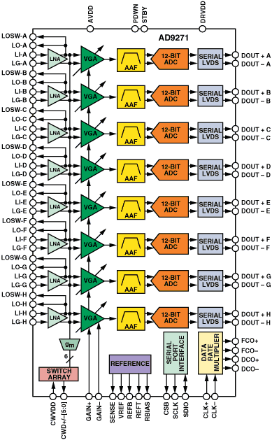
An essential subsystem from Analog Devices designed to satisfy the compactness requirement, the tiny, 14-mm × 14-mm × 1.2-mm, AD9271 (Figure 2) brings together all of the required signal chain blocks for acquiring eight channels of data, with a dramatic reduction in board space and power. In comparison to a solution employing discrete elements, the AD9271 reduces the total area per channel by more than 1/3, and power dissipation by more than 25%—consuming only 150 mW per channel at 40 MSPS. The AD9271 also offers a host of customizing options—available through a serial port interface—allowing further optimization of power and configurability, depending on the application.

The AD9271 embodies an 8-channel signal chain, each channel comprising a low-noise amplifier (LNA), variable-gain amplifier (VGA), antialiasing filter (AAF), and analog-to-digital converter. This is the receive chain commonly used to process return pulses in pulsed-wave mode: B-mode scanning for gray scale imaging, and F-mode, which is a color overlay on the B-mode display, to show blood flow. In pulsed-wave mode, the transducer alternates between transmission and reception in order to develop a periodically updated two-dimensional image.
Another common form of imaging is continuous-wave (CW) Doppler, or D-mode, for showing blood flow velocities and their frequencies. As the name suggests, the image is produced using continuously generated signals, where one-half the transducer channels are transmitting and the other half are receiving. CW has the advantage of measuring high velocities of blood flow accurately, but it lacks the depth and penetration found in traditional pulsed-wave systems. Since each method has its own benefits and limitations, depending on the application, modern ultrasound systems commonly use both modalities—and the AD9271 is applicable to both. In particular, it allows the user to operate in continuous-wave Doppler mode by employing an integrated crosspoint switch. This crosspoint switch allows channels of similar phase to be coherently summed into groups for phase alignment and summation. The AD9271 supports delay lines for low-end systems, and the AD8339 quad demodulator with programmable phase adjustment for the best performance. The AD8339 allows finer adjustments to phase alignment and summation in order to increase image accuracy. This device easily connects externally, allowing the user to compact more of the signal chain required for signals that need very large dynamic range.
Dynamic Range and Noise Requirements
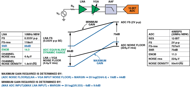
As the high-frequency acoustic signals penetrate through the body, they are attenuated by about 1 dB/cm/MHz. For example, with an 8-MHz probe and 4-cm depth penetration—and accounting for both outgoing and return attenuation—the signal amplitude variation from the internal tissues will differ by 64 dB (or 4 × 8 × 2) from reflections near the surface [Further Reading 2]. Adding 50 dB of imaging resolution, and accounting for losses due to bone, cables, and other mismatches, the desired dynamic range approaches 119 dB. To put this into perspective, a 0.333-V p-p full-scale signal with a 1.4-nV/rt-Hz noise floor in a 10-MHz bandwidth implies an 88-dB input dynamic range. Additional dynamic range is achieved by using multiple channels [10 × log(N channels)], e.g., 128 channels increases the dynamic range by 21 dB. This establishes a practical limit for dynamic range between 100 dB and 120 dB.
The achievable dynamic range is limited by the front-end components. Since the entire dynamic range is not needed at all instants of time, an ADC with less than full dynamic range can be used by sweeping the gain of the VGA to match the attenuation of the received reflection over time (proportional to depth of penetration). This is called time-gain compensation (TGC). The LNA sets up the equivalent dynamic range that can be mapped into the ADC. The AD9271 has an equivalent dynamic range of 88 dB in a 10-MHz bandwidth (158 dB/rt-Hz), allowing it to handle both very small and large signals (echoes) from the tissue being scanned, as shown in Figure 3. The full scale of the LNA should be large enough not to saturate from the near-field signal; and the lower the noise floor, the higher the dynamic range.

As power requirements must increase to handle lower noise levels, some compromise must be made in portable applications because of power constraints. While the 88-dB dynamic range of the AD9271 is better than competitive solutions, it is still less than higher-power VGA products, such as the AD8332, with its 0.72-nV/rt-Hz input-referred noise, as shown in Table 1. Notice that the AD8332 has the lowest input-referred noise and highest input dynamic range of the solutions shown. No one approach is ideal. Although digital processing is an essential feature of all solutions today, the specific implementation and choice of components are proprietary to each ultrasound manufacturer.
Table 1. Comparison of Solutions Using Analog Devices Components
| Product | LNA Input Range | LNA Input Noise | Total Channel Input Noise (without ADC) | Input Dynamic Range for Channel (@10-MHz BW) |
| AD8332 | 550 mV p-p | 0.74 nV/rt-Hz | 0.82 nV/rt-Hz | 97 dB |
| AD8335 | 625 mV p-p | 1.2 nV/rt-Hz | 1.3 nV/rt-Hz | 95 dB |
| AD9271 | 400 mV p-p 333 mV p-p 250 mV p-p | 1.4 nV/rt-Hz 1.2 nV/rt-Hz 1.1 nV/rt-Hz | 1.65 nV/rt-Hz 1.44 nV/rt-Hz 1.31 nV/rt-Hz | 89 dB 88 dB 87 dB |
Conclusion
For both medical and industrial applications, there is a growing trend towards portable ultrasound. All such systems have similar requirements for compactness and portability in remote locations. The AD9271 makes portability increasingly realizable by combining, in a tiny IC package, eight channels of the receive signal chain applicable to both pulsed- and continuous-wave Doppler systems. The AD9271 is destined to spawn a family of products providing options with lower power requirements or lower noise, pushing the boundaries even further in future generations.
参考电路
- Bandes, Alan. “How Are Your Bearings Holding Up? Find Out with Ultrasound.” Sensors Magazine. July 2006. pp. 24-27.
- Brunner, Eberhard. “How Ultrasound System Considerations Influence Front-End Component Choice.” Analog Dialogue 36. Part 1. 2002.
- Kisslo, Joseph A. and David B. Adams. Principles of Doppler Echocardiography and the Doppler Examination #1. London: Ciba-Geigy. 1987.
- Kuijpers, F. A. “The Role of Technology in Future Medical Imaging.” Medicamundi. 1995. Vol. 40. No. 3. Philips Medical Systems.
- Meire, Hylton B. and Pat Farrant. Basic Ultrasound. Wiley. 1995. pp. 1-66.


 客服微信
客服微信 查ic网订阅号

