

Introduction
The term short-range devICe (SRD) is intended to cover radio transmitters that provide either unidirectional or bidirectional communication and have little capability of causing interference to other radio equipment. One cannot list all the applications of SRDs, because they provide many different services. Among their more popular applications are:
- Telecontrol for home- or other building-automation systems
- Wireless sensor systems
- Alarms
- Automotive, including remote keyless entry and remote car-starting
- Wireless speech and video
Designers of SRD wireless systems need to use great care in choosing the radio’s communication frequency. In most cases, the choice is limited to those portions of the spectrum that allow license-free operation given that certain specifications and conditions on usage are met. Table I lists the frequency bands available globally.
Table I. Global SRD Frequency Allocations| Global Frequency | Allocations Comments |
| 13.56 MHz | Used for near-field communications |
| 40 MHz | Not often used, long range possible |
| 433 MHz | Need to reduce power for U.S. |
| 2.4 GHz | Popular global band |
| 5.8 GHz | Some systems up-banding from 2.4 GHz |
| Multiregion Allocations | Comments |
| 868 MHz/915 MHz | Available in Europe/U.S./Canada/Australia/NZ |
The 2.4-GHz band is widely used by designers who want to build systems that can operate worldwide. In fact, it has become the frequency band of choice for such standards as Bluetooth, WLAN, and ZigBee. The 5.8-GHz band has also attracted some attention—in cordless phones or the 802.11a version of WLAN, for example.
For systems that require both wider range and lower power, however, the sub-1-GHz bands remain compelling due to reduced co-existence issues and greater transmission range, as both of these affect power consumption—an important consideration in battery-powered applications.
The improvement in propagation range for lower-frequency radiators can be shown by a simplified version of the Friis transmission equation, which relates the power available in a receiving antenna, Pr, to the power delivered to the transmitting antenna, Pt:
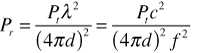
This equation assumes that both antennas have unity gain. It shows that, for a fixed transmit power, Pt, the received power will decrease with the square of the distance, d, and the square of the frequency, f (or increase with the square of the wavelength, λ). If the received power goes below the minimum power needed to demodulate the signal correctly (called the sensitivity point), the link will break down.
Worldwide Frequency Allocations Below 1 GHz
A more-detailed description of the various sub-1-GHz standards is given by Table II. It is not an exhaustive list, but more detail can be found by following the links provided in the table.
Table II. Some Common Regional SRD Bands| Region | Relevant Standards | Frequency Bands (MHz) | Relevant links |
| Europe | ERC REC 70-03 EN 300 220 (Sept. '00) EN 300 220 (Feb. '06) | 433.0 to 434.79 868.0 to 870 863.0 to 870 | http://www.ero.dk/ http://www.etsi.org |
| U.S. | FCC Title 47 Part 15.231 Part 15.247 | 260 to 470 902 to 928 | http://www.access.gpo.gov/nara/cfr/ waisidx_04/47cfr15_04.html |
| Canada | RSS-210 | 260 to 470 902 to 928 | http://strategis.ic.gc.ca/epic/internet/insmt-gst.nsf/en/sf01320e.html |
| Japan | ARIB STD-T67 | 426.0375 to 426.1125 429.175 to 429.7375 | http://www.arib.or.jp/english/ |
| China | RADIO REGULATIONS OF THE PEOPLE’S REPUBLIC OF CHINA | 315.0 to 316.0 430.0 to 432.0 | |
| Australia | AS/NZS 4268:2003 | 433.05 to 434.79 915 to 928 | http://www.acma.gov.au/ACMAINTER.131180 |
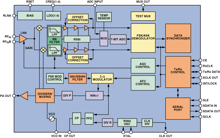
The 433-MHz band is one option for global usage, with a slight frequency modification required for Japan (easily handled by most modern frequency-flexible transceivers, such as the ADF7020—shown in Figure 1 below—or the ADF7021). Less than 2 MHz of bandwidth is available, however, and applications such as voice, video, audio and continuous data transmission are typically not allowed in this band, thus restricting its use. As a result, it is more commonly used for keyless entry systems and basic telecontrol.
The bands around 868 MHz (Europe) and 902 MHz to 928 MHz (U.S.) are more useful; they do not restrict applications, and they allow more compact antenna implementations. Other regions, such as Australia and Canada, have adopted versions of these specifications—thus making the band multiregional, albeit not quite fully global.
Prior to the latest EN 300 220 specification, however, the U.S. and European bodies took vastly different regulatory approaches. The U.S. adopted a frequency-hopping approach, while Europe applied duty-cycle limits in each of the subbands as described in the ERC REC-70 document. Both of these implementations are useful in minimizing interference, but manufacturers who were designing systems for both regions needed to completely rewrite the media-access layer (MAC) in the system’s communication protocol.
Fortunately, the latest European EN 300 220 regulations (due for release in February 2006) have extended the frequency bands to allow for frequency-hopping spread-spectrum (FHSS) or direct-sequence spread-spectrum (DSSS). This makes the MAC implementations more similar to those designed for the U.S, but some fine-tuning will still be required. The following sections describe some aspects of the new specification, covering areas that the SRD system designer needs to consider.
Frequency-Hopping Systems
The frequency-hopping spread-spectrum (FHSS) transmission technology spreads energy in the time domain by dividing the spectrum into a number of channels, switching between them in a pseudo-random sequence, or “hopping code,” that is known by both the receiver and transmitter. To welcome new nodes joining the network, the controller node periodically sends out a beacon signal to which the new node can synchronize. The synchronization time depends on the beacon interval and the number of hopping channels. U.S. and European standards both specify a similar number of hopping channels, and a maximum dwell time (the time spent at a particular frequency during any single hop) of 400 ms.
Table III shows the number of channels, effective radiated power (ERP), and duty-cycle requirement for the extended frequency band in Europe (below 870 MHz) when FHSS is used. Bandwidths of up to 7 MHz are available once either the listen-before-talk (LBT) or duty-cycle limits are met, as compared to the 2-MHz range available previously.
Table III. European Channel Requirements| Subband | Number of Hop Channels | Power/Magnetic Field | Other Requirements |
| 865 MHz to 868 MHz | ≥60 | ≤25 mV ERP | LBT or <1% Tx duty cycle |
| 863 MHz to 870 MHz | ≥47 | ≤25 mV ERP | LBT or <0.1% Tx duty cycle |
Listen-before-talk, a “polite” communication protocol, scans the channel for activity before initiating a transmission. Also called clear-channel-assessment (CCA), systems using it with frequency hopping have no duty-cycle limitations.
Wideband Modulation: DSSS
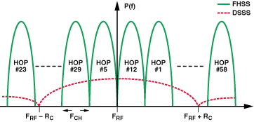
Besides FHSS, direct-sequence spread-spectrum (DSSS) is also addressed in the new European regulations. In a DSSS system, a narrow-band signal is multiplied by a high-speed pseudo-random number (PRN) sequence to generate a spread signal. Each PRN pulse is called a “chip,” and the rate of the sequence is called the “chip rate.” The extent to which the original narrow-band signal is spread is referred to as the processing gain; it is the ratio of the chip rate (Rc) to the narrow-band data symbol rate. Frequency spectra of FHSS and DSSS are compared in Figure 2.
At the receiver, the incoming spread-spectrum signal is multiplied with the same PRN code to despread the signal, allowing the original narrow-band signal to be extracted. At the same time, any narrow-band interferers at the receiver are spread and appear to the demodulator as wideband noise. The allocation of different PRN codes to each user in the system allows isolation between users in the same frequency band. This is known as code-division multiple access (CDMA).
A few examples of systems using DSSS modulation include IEEE 802.15.4 (WPAN), IEEE 802.11 (WLAN), and GPS. The main advantages of DSSS are:
- Interference resilience – The essence of the interference-rejection capability of DSSS is that the useful signal gets multiplied twice (spread and despread) by the PRN code while any interferers are multiplied just once (spread).
- Low power spectral density – Introducing minimal interference with existing narrow-band systems.
- Security – Very resistant to jamming because of spreading/despreading.
- Mitigation of multipath effects
Wideband Modulation Other than DSSS or FHSS.
An interesting aspect of the new European regulations is that they provide for other wideband spread-spectrum modulation schemes in addition to FHSS and DSSS. FSK/GFSK (Gaussian frequency-shift-keying) modulation, with an occupied bandwidth greater than 200 kHz, is considered wideband modulation under the European regulations. Table IV highlights the main specifications which apply to wideband modulation schemes (including DSSS) in Europe:
Table IV. Maximum Radiated Power Density, Bandwidth, and Duty-Cycle Limits for Spread-Spectrum Modulation (Other than FHSS) and Wideband Modulation| Subband | Occupied Bandwidth (99%) | Maximum Radiated Power Density | ERP Requirement |
| 865 MHz to 868 MHz | 0.6 MHz | 6.2 dBm/100 kHz | 1% Tx duty cycle |
| 865 MHz to 870 MHz | 3.0 MHz | –0.8 dBm/100 kHz | 0.1% Tx duty cycle |
| 863 MHz to 870 MHz | 7.0 MHz | –4.5 dBm/100 kHz | 0.1% Tx duty cycle |
An example of a device that can take advantage of this wideband standard using FSK modulation is the ADF7025 ISM-band transceiver IC. To operate in the 865-MHz to 870-MHz subband, the design must comply with the maximum occupied bandwidth (99%) and maximum power density limits. An edge-of-channel (or band) maximum power limit of –36 dBm is also specified.
With the ADF7025 set up as shown in Table V, all three of these limits were met. Figure 3 shows the occupied bandwidth as 1.7569 MHz and the peak spectral density as –1.41 dBm/100 kHz.
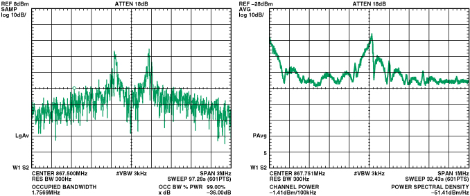
| Frequency | 867.5 MHz |
| Modulation | FSK |
| Frequency Deviation | ±250 kHz |
| Data Rate | 384 kbps |
The ADF7025, using wideband modulation, has the possibility of a high data rate (in this case 384 kbps), allowing transmission of audio and medium quality video (several frames per second) in the sub-1-GHz European ISM frequency bands.
The U.S. regulation (FCC Part 15.247) has an allocation similar to that of Europe, which provides for frequency-hopping systems operating in the 902 MHz to 928 MHz, 2400 MHz to 2483.5 MHz, and 5725 MHz to 5850 MHz bands, while also providing for “digitally-modulated” signals. This is a loose term that covers both spread-spectrum (DSSS) and other simpler forms of modulation (such as FSK, GFSK), and is thus similar to the “wideband modulation” specification in the European regulations. The two main requirements are:
- The minimum 6-dB bandwidth shall be at least 500 kHz.
- For digitally-modulated systems, the power spectral density conducted from the intentional radiator to the antenna shall not be greater than 8 dBm in any 3-kHz band during any time interval of continuous transmission.
Anyone wishing to employ a system other than FHSS would normally have to limit the field strength to 50 mV/m (–1.5 dBm ERP). But in the case of “digital modulation” the maximum output power is 1 W, once the maximum power spectral density limit is met. Therefore, using the ADF7025 with an FSK frequency deviation wide enough to ensure that the 6-dB bandwidth is greater than 500 kHz, permits a 1-W ERP. Also, with the wide signal bandwidths, higher data rates are possible (maximum 384 kbps for the ADF7025).
The ADF7025’s co-channel rejection varies in the co-channel from –2 dB (worst case) to +24 dB, depending on the bandwidth of the interferer. This can be compared with a commercially available 802.15.4 DSSS transceiver, which has a co-channel rejection of –4 dB, where the jamming signal is an IEEE 802.15.4-modulated signal.
Using these methods, similar wideband modulated systems can now be employed in both the U.S. and Europe, thus simplifying the engineering of products intended for worldwide markets. The ADF7025 transceiver architecture lends itself to operation in both the “digital modulation” mode as defined in the U.S. standards and the “wideband modulation” mode as defined in the new European regulations.
Transient Power Requirements
Engineers should also be aware of a new specification in the European regulations that imposes restrictions on transient power, which is defined as the power falling into the adjacent spectrum when the transmitter is switched on and off during normal operation. This limit has been added to the latest regulations to prevent spectral splatter.
As the current to the power amplifier (PA) increases (turning on) or decreases (turning off), the load seen by the voltage-controlled oscillator (VCO) changes, causing the phase-locked loop (PLL) to unlock for an instant and produce spurious emissions—or spectral splatter—while the loop seeks to reacquire lock. In systems where a unit only transmits at intervals, the splatter can significantly increase the power falling into neighboring channels.
Figure 4 highlights the problem of spectral splatter. The yellow trace shows the PA output spectrum from an ADF7020 transmitter when the PA is turned on and off once every 100 ms while the spectrum analyzer is kept on maximum hold. It is evident that significant power is falling into channels on either side of the carrier. The blue trace shows the PA output being ramped on and off in 64 steps every 100 ms, and indicates a considerable reduction of the power falling into the neighboring channels. Specification 8.5 of the latest EN 300 220 regulation establishes a limit on the amount of power falling into these adjacent channels.
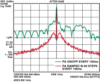
The measurement procedure requires that the transmitter be turned on and off five times at maximum output power; and that the power falling into the second, fourth, and 10th channels on either side of the carrier is measured.
The simplest way to ensure compliance with this specification is to ramp the PA gradually off-to-on or on-to-off. This is normally accomplished by using the microcontroller to turn the PA on/off in stages. With the ADF7020 transceiver, it is possible to step the PA from off to +14 dBm in a maximum of 63 steps. A faster and simpler approach is to use a transceiver with an automatic PA ramp. The ADF7021 has a programmable ramp for which both the number of steps and duration of each step can be set by the user.
Communication Protocol Considerations
Analog Devices is currently in the process of updating the ADIismlink (Version 2.0) protocol software, which can be used with any of the ADF702x transceivers. This protocol, intended for use in the worldwide sub-1-GHz bands, incorporates the new European regulations. It is based on a star-type network (with up to 255 endpoints) illustrated in Figure 5.
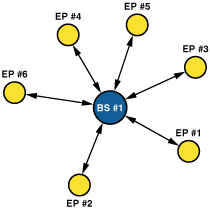
At the heart of the protocol is a nonslotted, nonpersistent carrier-sense multiple-access scheme with collision avoidance (CSMA-CA). The endpoint (EP) listens to the channel before transmitting (LBT), thereby avoiding collisions.
The nonslotted aspect of the protocol means that EPs can transmit as soon as they have data, subject to first performing a listen-before-talk operation. This approach also ensures that no synchronization is required. If an EP senses the channel is busy, it backs off for a random period before performing another LBT. The number of times this back-off can occur is limited, hence the nonpersistent nature of the protocol. In FHSS mode, the protocol uses this CSMA-CA system on each hopping channel, thus fulfilling the LBT requirement for the new European regulations.
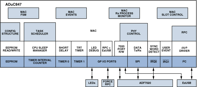
The physical-layer (PHY) and media-access-layer (MAC) parameters of the ADIismlink protocol are highly configurable, thus allowing thorough device- and system evaluation. Source code is also provided, simplifying the system-development procedure. The protocol comes as part of the ADF702x Development Kit (ADF70xxMB2). A system overview of ADIismlink is shown in Figure 6. More information on this is available through the ADI website.
Conclusion
The new European regulations impose very specific requirements for over-the-air protocols in the 863-MHz-to-870-MHz band. Whether a system uses a single-channel protocol, FHSS, or DSSS, there are specific rules that must be observed. This of course complicates the protocol design. However, the upside of these new ETSI regulations is that they mirror the FCC Part 15.247 regulations in many aspects, thus simplifying the design of a protocol intended for multiregion use. In addition, the Analog Devices development kit includes protocol examples to simplify the challenges involved in designing short-range wireless networks.


 客服微信
客服微信 查ic网订阅号