

We increasingly encounter radio-frequency identifICation (RFID) systems in our lives and work. From inventory control to fast checkouts at the supermarket, the technology is transforming many existing applications and enabling new ones. At the front end, the "signal chain" starts with small tags attached to the units of interest; the tags convey information in the form of a bit stream to an RFID reader that detects when tags are present in a specific area, and reads the information they carry. At the back end, a server-based system maintains and updates the tag database, generating alerts or initiating other information-based processes within the enterprise.
Most RFID readers currently employ more than one processor to satisfy application requirements. Typically, a signal processor is interfaced to an analog-to-digital converter (ADC) and a digital-to-analog converter (DAC). Then a network processor communicates with a local or remote server for information storage and retrieval. This article describes how these seemingly disparate functions—signal conversion and network connectivity—can be managed by a single processor from the Analog Devices Blackfin processor family.
We start with a brief overview of RFID technology, and discuss the present and future applications it enables. Then, focusing on RFID reader functionality, we explore the basic software components that need to run on the RFID reader—as well as the server connections. Finally, some block diagrams offer a few suggestions for system configurations.
Today's Applications and Emerging Applications
RFID technology enables many new types of applications by allowing concurrent monitoring of multiple items, without requiring a person to “touch” each one (with a hand-held barcode scanner, for example). The kinds of applications that can take advantage of this automated identification include diverse areas such as inventory control, logistics management, surveillance, and toll collection.
Today, the ubiquitous merchandise-oriented universal product code (UPC), a one-dimensional (1D) barcode, graces nearly everything available for public purchase. The barcode contains relevant information about the item to which it is attached, perhaps including the item’s suggested retail price and/or the place and date of manufacture. 1D and 2D barcodes can also be used to track shipment details for an item.
Barcodes work well for individual items, but the workflow becomes less efficient when there are many things to scan. For example, it’s impractical to open and individually scan every item on a pallet that contains hundreds or thousands of end products. But even when there are relatively few items to scan, such as groceries at the supermarket checkout, proper alignment must be established between the scanner and the label being scanned. What’s more, manipulating a large item to find the barcode can be challenging.
RFID technology replaces the UPC with an EPC (Electronic Product Code), in the form of a stream of bits. At a minimum, an EPC allows the same type of information contained in a barcode to be collected automatically and accessed remotely, with minimal human intervention. In addition, an EPC can include much more information relating to unique identifying characteristics of the tagged item, even if there are many identical items. Moreover, unlike a conventional barcode, it doesn’t matter in which direction the items are facing, or what the ambient lighting conditions are—the items can be still be detected and tracked. Fog, darkness, and even warehouse grime no longer matter.
Here are some more ways in which RFID systems are used today:
- In supermarket food pallets and cases, they can track the assets and allow better management of the asset pool. With the ability to write to the tag, additional information (e.g., sell-by date) can be included. In addition, automatic reordering can be implemented to keep shelves properly stocked.
- In libraries they can be used to automate the issuance and return of materials that, in earlier times, were identified by reading labels individually with a barcode scanner.
- In clothing labels they can identify the true item source. By using the tag’s identification number, the item can be certified as authentic or singled out for investigation as counterfeit.
- In the pharmaceutical industry they can be used to safeguard against counterfeit supplies.
- In sports competitions they can accurately track a runner’s progress during a long race.
RFID System Overview
RFID uses radio-frequency (RF) transmissions of bit streams to communicate with, identify, classify, and/or track objects. Each object has its own RFID tag (also known as a transponder). The overall system employs a tag reader, a subsystem that receives RF energy from each tag. The reader has embedded software that manages the interrogation, decoding, and processing of the received tag information; and it communicates with a storage system that houses a tag database and other relevant information. Figure 1 shows a conceptual diagram of an RFID system.
RFID Readers
The RFID reader provides the connectivity between individual tags and the tracking/management system. Available in a variety of form factors, it is typically small enough to be mounted on a counter, tripod, or wall. Depending on the application and operating conditions, there may be a multiplicity of readers to fully service a specific area. In a warehouse, for example, a network of readers can ensure that 100% of all pallets are queried and logged as they pass from point A to point B.
Overall, the reader provides three main functions: bidirectional communication with the tags to isolate individual ones; initial processing of received information; and connection to the server that links the information into the enterprise.
The RFID reader must deal with multiple tags within the field of interest—a very important consideration in applications with many tags within a confined spatial area (for example, multiple tagged products residing on numerous factory pallets).
The primary challenge in a multiple reader/tag scenario is that collisions will occur when many readers send out queries and multiple tags respond at the same time. The most common way to avoid this problem is to use some form of time-division multiplexing algorithm. Readers can be set to interrogate at different times, while tags can be configured to respond after a random time interval. It is clear that having the ability to implement this function in embedded software provides additional flexibility.
RFID Transponders ("Tags")
An RFID tag consists of an integrated-circuit (IC) chip holding unique information (such as EPC data) about the object to which the tag is affixed, an antenna (usually a printed circuit pattern) for receiving RF energy from the reader and for transmitting information, and some kind of housing that envelops the tag’s components. It’s worth remembering that the above term “object” can apply to any number of different things, from factory goods to animals, to people. The distance from the tag to the reader, an important system variable, is directly influenced by the tag technology. Tags can be passive, active, or semi-active.
Passive Tags
Passive tags are the simplest type. Powered exclusively by RF energy sent from the reader, they don’t have an integrated battery, so they can be inexpensive, mechanically robust, and quite small (e.g., about the size of a thumbnail). Passive tags have a limited reader-to-tag range, however, because the received power depends on their physical proximity to the RFID reader.
The range of the link is also affected by the RF frequency chosen. Low-frequency (LF) tags commonly utilize the 125-kHz-to-135-kHz portion of the spectrum; since their range is constricted, they are mainly used for access control and animal tagging. High-frequency (HF) tags, mostly operating in the 13.56-MHz band, allow a range of a couple of feet. They are typically used for simple one-on-one object reads, such as access control, toll collection, and tracking of portable items, such as library books.
UHF tags, on the other hand, operate at frequencies from 850 MHz to 950 MHz and have a considerably longer range—10 feet or more. Moreover, because of the potentially wider bandwidth available, a reader can interrogate many of these tags at a time, as opposed to the one-on-one tag-reading process at lower frequencies. This trait helps minimize the need for multiple readers in a given zone, making UHF tags very popular in industrial applications for inventory tracking and control. However, UHF tags are unable to penetrate liquids efficiently, a major disadvantage, making them less useful for liquid-filled objects such as beverages and humans. For tracking these items, HF tags are often used instead.
In a 2004 survey of passive tag suppliers, the price of UHF tags was predicted to reach 16 cents per tag in 2008, down from 57 cents in 2003—thus continuing to make tagging items a cost-effective approach to asset and inventory tracking.
Semi-Active Tags
Like passive tags, semi-active tags reflect (rather than transmit) RF energy back to the tag reader to send identification information. However, these tags also contain a battery that powers their ICs. This allows for some interesting applications, such as when a sensor is included in the tag. In addition to static identification data, each transponder can transmit real-time attributes, such as temperature, humidity, and timestamp. By using the battery only to power a simple IC and sensor—and not including a transmitter—the semi-active tag achieves a compromise between cost, size, and range.
Active Tags
Active tags go one step further, by powering both the tag IC (along with any sensors) and the RF transmitter, using an integrated battery. Being self-powered, they can operate over a much larger reader-to-tag range (up to 100+ meters), which also translates into allowing goods to move past the reader much faster than in the case of passive or semi-active tag systems. In addition, active tags can carry much more product information than just an EPC code.
On the downside, the battery shortens the life of an active tag and drives up both its cost and size. Active tags commonly operate in the 433-MHz and 2.4-GHz industrial-, scientific-, and medical (ISM) bands, which are available throughout most parts of the world. Consequently, as more wireless consumer products appear with 2.4-GHz-based 802.11 and Bluetooth® modules, co-existence between active tags and these devices becomes an important issue.
Software Architecture of the RFID Reader
Having described the basic functionality of an RFID reader, we now consider how to implement the reader with Blackfin-type convergent processors. The three elements of the RFID reader software architecture are: the back-end server interface, the middleware, and the front-end tag reader algorithms. Though distinct, all these elements of the software architecture can run concurrently on a single Blackfin processor.
Back-End Server and Connectivity
Often, the RFID reader contains a networking element—wired Ethernet (IEEE 802.3), wireless Ethernet (IEEE 802.11 a/b/g), or ZigBee™ (IEEE 802.15.4), for example—that connects single RFID-read events to a central server. The central server runs a database application, with functions that include matching, tracking, and storage. In many applications, an “alert” function is also present (the re-order trigger, for supply chain and inventory management systems, or an alert to a guard, for security applications).
Incidentally, a reader built around a high-performance embedded processor that runs µClinux (also uClinux) has a substantial advantage over one that doesn’t when communicating with a back-end server. The presence of a robust TCP/IP stack and the availability of SQL database engines greatly reduce an otherwise major integration burden in the development process.
Middleware
The term middleware, as employed in RFID, has a somewhat different definition from its use in other embedded systems. In RFID terms, middleware is the software translation layer between the front-end RFID reader and the back-end enterprise system. The middleware filters the data from the reader and ensures that it is free of multiple reads or bad data. In early RFID systems, the middleware ran on the server, but the filtering of RFID data is now often performed on the reader before sending it through the enterprise’s network. This degree of increased functionality is another advantage embedded processors bring to this application space.
Front End of the Reader
The system’s filter- and transform-intensive signal processing, occurring in the front end of the reader, requires a device with the kind of strong signal-processing performance typically associated with Blackfin processors.
A/D and D/A Converters Now that we have a general sense of an RFID system’s components, let’s focus on connectivity from the RFID reader’s viewpoint. For communicating with a tag, the mixed-signal front-end (MxFE®) IC forms the interface of interest.
MxFE devices are general-purpose, intermediate-frequency subsystems that include A/D and D/A converters, low-noise amplifiers, mixers, AGC circuitry, and programmable filters. Output streams of I&Q data connect directly to processor parallel ports. Analog Devices MxFE IC family members constitute the highest performance narrow-band receivers available, well-suited to RFID—and other—applications.
Figure 2 shows a block diagram of a typical MxFE device.
Blackfin Processors for RFID Applications
Blackfin processors provide connectivity to both wired and wireless networks. Some processors, such as the ADSP-BF536 and ADSP-BF537, have a 10-base-T/100-base-T Ethernet MAC on chip. On the wireless side, all Blackfin processors can connect directly to both 802.15.4 ZigBee and IEEE 802.11 chipsets via the SPI® and SPORT peripherals. Line-speed transfers can be obtained without consuming the entire processor bandwidth.
In addition, Blackfin processors include a parallel peripheral interface (PPI), which can connect directly to ADCs and DACs such as those mentioned above. Some Blackfin processors include two PPIs, which can expand system functionality even further—allowing a camera to be connected to an RFID reader, for instance. Besides RFID applications, these Blackfin features are also especially attractive for 1D and 2D barcode applications, because of Blackfin’s ability to perform system control, networking, and image processing on the same device.
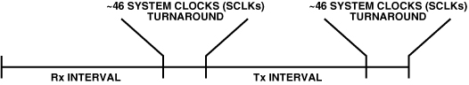
For RFID applications, a single PPI is often sufficient because of the way the RFID reader interrogates tags. First, the PPI is configured in transmit mode, and the processor sends a digital sequence to a DAC. The transmitted sequence is converted to an analog signal, which is then upconverted and sent out to excite/wake up local RFID tags, which then respond. Simultaneously, the PPI is reconfigured as a receiver in a small number of processor system clock pulses (see EE-Note 236), as shown in Figure 3. In this way, a downconverted RF signal can be sampled by an ADC and brought into the Blackfin directly. In the figure, the time between each receive (Rx) and transmit (Tx) interval is measured in system clock cycles. The elapsed time allows for the transmitted signal to reach the tag and for the tag to transmit a response.
In some RFID applications, a Blackfin processor alone can act as the server—for example, when large data stores and database manipulations are not necessary. For instance, imagine an elderly parent wearing a bracelet with a tag that could be monitored within the house. If no signs of activity were noted within a specified time interval, the monitoring agency could alert registered friends or relatives.
The software components that make up the infrastructure of a Blackfin RFID reader are available on the Blackfin.uClinux.org website. This offering includes the drivers necessary to interface to the mixed-signal, front-end IC, as well as a DMA driver that is very useful in moving data through a system. The µClinux-based network stack and SQL database engines are also available. From a system perspective, additional features, such as 802.11 Wi-Fi cards, USB thumb drives, and CompactFlash card interfaces, can very quickly be integrated with Blackfin devices. For more information, refer to http://blackfin.uclinux.org.
RFID SYSTEM EXAMPLES
Wired RFID Systems
The most common application of RFID is asset management, which benefits by reduction of lost inventory, elimination of incorrect deliveries, improvement in distribution logistics, and lessening of stock-outs—as the result of being able to track a pallet’s movement through the warehouse. An RFID system in a large warehouse can track a container-laden pallet’s movement from the time the pallet enters the warehouse to the time it leaves. Such a system relies on fixed RFID readers placed throughout the warehouse and at points of inbound/outbound shipping.
As a means of simplifying wired infrastructure, Power-over-Ethernet networks (PoE) are ideal for these types of applications. IEEE 802.3a/f PoE deals with networked systems in low-power applications. A PoE system, like the one shown in Figure 4, consists of power-sourcing equipment (PSE) and a powered device (PD). The PSE provides power down the Ethernet line, while the PD (for the purpose of this discussion) constitutes the convergent networked processor and its surrounding components. PoE has a recommended maximum cable length of 100 meters, which is suitable for many embedded RFID applications, due to its relative mobility and elimination of the cost associated with installing conventional ac wiring and outlets.
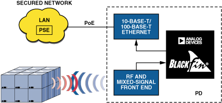
A network processor supporting embedded RFID applications requires sufficient performance and integration to handle a sophisticated multilayer IP stack, in addition to the RFID acquisition software. The ADSP-BF537 Blackfin processor—which includes a 10-base-T/100-base-T Ethernet MAC—is a good example of such integration. For example, many Ethernet PHY devices provide a status pin with the capability to interrupt upon a status change. This feature is seamlessly integrated with Blackfin interrupt functionality to yield a robust, power-efficient system.
Wireless RFID at Low Cost
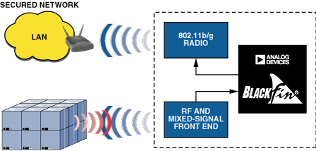
For applications such as a forklift-mounted scanner or a portable hand-held scanner, where wired or PoE operation is not possible, wireless protocols like IEEE 802.11b/g allow RFID readers to connect to a wireless access point, as shown in Figure 5. Blackfin processors can connect to 802.11 chipsets via either serial or parallel interfaces. In addition, because of their computational horsepower, these processors support both split-MAC and full-MAC 802.11a/b/g implementations. For example, a full-MAC might be needed for system integration of a CompactFlash 802.11b card, which interfaces through Blackfin’s asynchronous memory port. A split-MAC implementation typically interfaces through a SPORT or SPI interface—the lower MAC resides on the wireless chipset, while the upper MAC is executed in Blackfin software.
While their stack and processing requirements can be easily handled on a single-core processor, wireless applications are testing the boundaries of performance vs. power consumption. Managed power consumption, offering scalable performance based on application requirements, is achievable using the dynamic power management capabilities of low-cost convergent processors such as the ADSP-BF531. These dynamic power modes are designed to enable flexible performance and power arrangements for just about any networked system.
High-Performance Systems
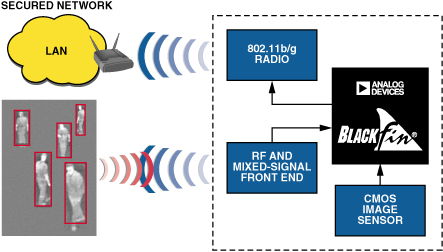
In emerging applications, RFID technology is pairing up with additional devices such as biometric sensors or CMOS image sensors. As Figure 6 shows, in advanced applications of security authorization and personnel access control, RFID combines with image analysis to ensure that, in a secure environment, not only are there exactly N people in the room, but they are all “authorized personnel.”
The computational demands of applications of this sort are ideally suited for handling by dual-core convergent processors such as the ADSP-BF561. An additional processor core not only effectively doubles the computational load that the device can handle; it also provides some surprising structural benefits that aren’t immediately obvious.
Traditionally, a dual-core processor employs discrete, and often different, tasks running on each core. For example, one core might perform all control-related tasks—such as networking, interfacing to bulk storage, RFID acquisition, and overall flow control. This core is also where the operating system or kernel will likely reside. Meanwhile, the second core can be dedicated to the high-intensity processing functions of the application. For example, the video-processing piece of the human-recognition algorithm might run on the second core, and the resulting data packets might be passed to the first core for transmission over a network interface.
The dual-core ADSP-BF561 contains both dual high-speed L1 instruction and data memories (local to each core), and a shared L2 memory between the two cores. Each core has equal access to a wide range of peripherals—video ports, serial ports, timers, and the like. As outlined above, one core of an ADSP-BF561 can manage the RFID acquisition and networking components, while the other core can be dedicated to image classification systems that can detect, classify, and track objects in real time.
µClinux
The µClinux operating system is a popular choice for facilitating both network connectivity—which is the largest software component of the reader—and the critical requirements of robustness and standards compliance. When reading RFID tags, it is essential to ensure that real-time requirements are met. Since the µClinux scheduler is not strictly real-time, it can be replaced with the ADEOS real-time scheduler, which safely holds off µClinux interrupts until the real-time critical processing is finished. This means that the front-end reader software can execute from the ADEOS domain in real time, while the middleware and back-end server interface can run in the traditional µClinux environment. This division gives the user hard real-time control of the application, while at the same time allowing access to all the benefits of open-source software. For more information about µClinux or ADEOS, see the Blackfin µClinux Wiki.
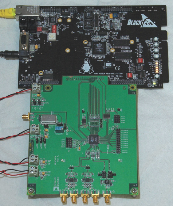
Figure 7 shows an Analog Devices MxFE evaluation board connected to a Blackfin ADSP-BF537 STAMP development platform, which runs the MxFE driver code, µClinux operating system, and TCP/IP network stack.
Conclusion
As we have shown, RFID applications no longer require both a dedicated signal processor for ADC/DAC interfacing and a microcontroller for networking. A convergent processor from the Blackfin family can handle the networking and control, with plenty of performance to spare for converter interfacing and pattern matching algorithms. This, in turn, leads to lower-cost Bills of Material and faster time-to-market for the next wave of RFID applications.


 客服微信
客服微信 查ic网订阅号